Contents
- Introduction
- Sustainable drainage systems (SuDS)
- The management train
- Design principles
- Construction
- Maintenance requirements
- Sustainable drainage systems components
- Planning application requirements
- Example drainage calculation scenarios
- Contact details
1. Introduction
Local planning policies and decisions on planning applications relating to major development must ensure that sustainable drainage systems, for the management of surface water runoff, are put in place unless demonstrated to be inappropriate.
Major development is defined as;
- developments of ten dwellings or more
- development residential site is over half a hectare
- building floorspace exceeds 1000m2 / 0.1 hectares
- equivalent non-residential or mixed development over a hectare or building over 1000m2
This guidance note details our requirements in our capacity as the lead local flood authority. It provides direction to the relevant design guidance for the successful implementation of sustainable drainage systems and is the basis on which planning consultations from local planning authorities will be assessed. Although developments should seek to fulfil the requirements of this drainage guidance, development sites may still be evaluated individually.
North Yorkshire is a large and varied county which incorporates seven council districts and local planning authorities. Three water authorities and five internal drainage boards also operate within North Yorkshire and may impose further restrictions in terms of flood risk and drainage which should also be considered as part of any development proposals.
2. Sustainable drainage systems
Sustainable drainage systems mimic natural drainage patterns and provide water quantity (flooding), water quality (pollution), amenity and biodiversity benefits.
The SuDS Manual C753 published by CIRIA provides guidance on the planning, design, construction and maintenance of sustainable drainage systems.
See also:
- rainfall runoff management for developments
- susdrain the community for sustainable drainage
- UK SuDS Tools website - HR Wallingford
- BS8582:2013 Code of Practice for Surface Water Management for Development Sites
- Building Regulations 2010 Section H3 Rainwater Drainage 2015 edition
- DEFRA Non-Statutory Technical Standards for Sustainable Drainage Systems
- Local Authority SuDS Officer Organisation (LASOO) Non-Statutory Technical Standards for Sustainable Drainage Practice Guidance
- Our supplementary infiltration guidance
3. The management train
A concept fundamental to implementing a successful sustainable drainage systems scheme is the management train. This is a sequence of sustainable drainage systems components that serve to control runoff rates and volumes and reduce pollution. The hierarchy of techniques to be used is:
Prevention: Prevention of runoff by good site design and reduction of impermeable areas.
Source control: Dealing with water where and when it falls (for example, infiltration techniques).
Site control: Management of water in the local area (for example, swales, detention basins).
Regional control: Management of runoff from sites (for example, balancing ponds, wetlands).
4. Design principles
The three most important requirements are:
- ensure that people, property and critical infrastructure are protected from flooding
- ensure that the development does not increase flood risk on or off site
- ensure that sustainable drainage systems will be economically maintained for the lifetime of the development
4.1 Runoff destinations
Surface water runoff not collected for use must be discharged to one or more of the following in the order of priority shown in accordance with the Building Regulations Part H:
a) Discharge into the ground (infiltration).
b) Discharge to a surface water body.
c) Discharge to a surface water sewer, highway drain or other drain
d) Discharge to combined sewer.
4.1.1 Discharge into the ground
All developments should seek to dispose of surface water via infiltration before the use of connections to local watercourses or sewer can be established, as per the drainage hierarchy as set out in the Building Regulations Part H. This will require the developer to carry out a detailed intrusive site investigation and hydrogeological review to determine the potential for surface water disposal by infiltration.
Where soil conditions appear favourable, then infiltration testing must be completed to determine the viability of soakaways on site. Testing should be undertaken to BRE 365 Digest standards. This requires infiltration tests to be performed successively three times in the same trial pit without using extrapolation. Test pits should ideally be sized and located to represent the proposed soakaway construction. Where infiltration test results differ over the site, the lowest calculated value should be used for design purposes.
For larger sites with multiple soakaways additional consideration should be given to the location and number of trial pits required. To ensure results are representative of the site and to reduce the risk of additional testing being requested, please contact the lead local flood authorities as early as possible to discuss the proposals.
Where test pits could be unstable, such as in loose sandy gravelly soils, then they should be lined with a suitable geotextile and filled with gravel or cell crate units and fitted with a filling and dipping tube prior to testing.
Viable infiltration rates for the use of soakaways are typically as low as x10-5 m/sec, and values that achieve this rate should generally use infiltration as the means of disposal of surface water drainage. Sites with infiltration rates below x10-5 indicate poorly draining soils and the developer should evaluate the practical aspects of locating adequately sized soakaway storage; available space and suitability of infiltration techniques will vary from development to development. For sites where infiltration rates are low, the developer should carefully consider risk of failure and the anticipated design life of the soakaways and adjustment of design safety factors may be required in mitigation.
The base of infiltration systems should be at least 1m above maximum anticipated groundwater levels to retain a working infiltration zone for the sustainable drainage systems scheme as per the BRE 365 Soakaway Design document. Groundwater should not rise to the level of the base of the soakaway during annual variations in the water table. Groundwater levels should be assessed for their variability where fluctuations in groundwater level may cause a problem in the long-term for any proposed depth of excavation. British Geological Society borehole and susceptibility to groundwater flooding datasets should be reviewed. On high risk sites, where groundwater levels could fluctuate significantly, the developer should also provide six months ground water monitoring that should include monitoring over the winter months.
Soakaways will require a 5m easement from all proposed and existing roads and buildings. More information in BRE 365 Digest and Building Regulations Part H. Soakaway storage should not be located under boundary features such as fences.
Within the design calculations of the proposed soakaways, an appropriate factor of safety must be applied generally in accordance with Ciria SuDS Manual Table 25.2. For the vertical sides of the structure a minimum factor of safety of two should be applied to the calculated design infiltration rate. Deterioration of soils should also be considered and further mitigation such as higher safety factors may be required.
In accordance with the Ciria SuDS Manual Section 25.4, a design infiltration rate of no greater than x10-5 m/sec should be used for the base of an infiltration structure or basin to allow for the long-term build-up of silt. This should be adjusted accordingly prior to applying the global factor of safety in calculations.
Drain times for soakaways should be assessed in accordance with the Ciria SuDS Manual Section 25.7 and the half drain times for the critical duration 30 years and 100 years plus climate change should be demonstrated to be no more than 24 hours. Where the developer proposes longer half drain times for the 100 year plus climate change event this should be agreed with the local lead flood authority.
Soakaways and other forms of allow for the long-term build-up of silt. This should be adjusted accordingly prior to applying the global factor of safety in calculations.
Drain times for soakaways should be assessed in accordance with the Ciria SuDS Manual Section 25.7 and the half drain times for the critical duration 30 year and 100 year plus climate change should be demonstrated to be no more than 24 hours. Where the developer proposes longer half drain times for the 100 year plus climate change event this should be agreed with the local lead flood authority.
Soakaways and other forms of sustainable drainage systems should be designed to be useable and maintainable for the lifetime of the development, with appropriate access available and management systems in place, be that a management company, water authority or private ownership.
Private owners of sustainable drainage systems schemes should be made aware of the maintenance requirements of sustainable drainage systems that they own, and arrangements put in place to ensure that responsibility is clear for future owners.
As noted in Ciria C753 section 25.2.1, infiltration values less than x10-6 are to be regarded as unviable for disposal of surface water development runoff and should be discounted as the sole means of surface water disposal.
Summary of acceptable infiltration rates for development surface water drainage (m/sec)
| Infiltration rate (m/sec) | Suitability | Tests to undertake |
|---|---|---|
| Greater than x10-6 | Appropriate for soakaways | Tests to undertake: Infiltration tests to BRE 365 standards and information of the ground conditions and groundwater levels. |
| Equal to x10-6 | Borderline | Tests to undertake: Infiltration tests to BRE 365 standards, plus a comprehensive ground investigation report, with groundwater levels. Subject to approval. |
| Less than x10-6 | Not Viable | Tests to undertake: Seek alternative means of disposal of surface water. |
4.1.2 Discharge to surface water body
Discharging to a watercourse will require a suitable natural watercourse or ditch in close proximity to the site for development flows to discharge into, subject to agreement with the landowner, local lead flood authority, internal drainage board or Environment Agency. Watercourses that are further away from the development site may still be used as a discharge point if access is available via a natural gravity fed outfall and permission gained from the appropriate landowner. Consideration must be given for the wider catchment and drainage network.
Developers must ensure the receiving waterbody is suitable for the disposal of surface water and that a positive connection to the wider surface water drainage network exists; in order to demonstrate that a new connection is not going to increase flood risk elsewhere. A capacity and condition survey should therefore be undertaken on receiving ditches/culverts and watercourses (on or off site), including the identification of the final outfall location. The survey results should be appropriate to the development and include details to demonstrate how any identified remedial items will be dealt with.
Access to any watercourse within the development will be required for maintenance therefore a no development stand-off zone of 5m from the top of the watercourse bank will be required. Local planning authorities may set a no development zone from any watercourse as part of their local development plan and you should contact them directly to discuss this. Internal drainage boards and the Environment Agency will specify easement requirements for assets under their jurisdiction.
As part of the drainage proposals, there is a presumption against culverting of watercourses and is preferable to re-naturalise culverted watercourse, in line with the Environment Agency’s general policy regarding culverts. More information in the Environment Agency Fluvial Design Guide, Chapter 8. If a culverted watercourse is to remain on a development site there must be a 3m easement to both sides of the culvert, similar to a sewer easement, to prevent possible damages to the culvert.
New connections to a water body or drainage system must not increase flood risk elsewhere, and development peak flow rates must be restricted to the pre-development QMED/QBAR runoff rate) greenfield runoff rates. See Section 4.3 on flood risk. Segregation and management of long term storage and use of higher discharge rates is in practice difficult to achieve and at the current time is an approach that is non-preferred by the local lead flood authority, where developments propose these techniques then the application will be assessed on an individual basis.
4.1.3 Discharge to a surface water sewer, highway drain or other drain
Discharging development flows to a separate surface water sewer is preferred over a combined sewer connection. Agreements will be required by the regional water authority for connection to the public sewer system, this may involve additional restrictions by the receiving water authority.
Our Highways team only accept surface water flow from the development highway into a highway drain maintained by ourselves and surface water from open land and watercourses are not accepted. We also adopt sustainable drainage systems for the sole purpose of highway drainage flows, discussions and agreements with our highways should be sought as early as possible in the development stage.
4.1.4 Discharge to combined sewer
Connection to a public combined sewer can only be used as a last resort for the development surface water runoff and all other options should be thoroughly explored before connection to a combined sewer can be considered.
4.2 Greenfield or brownfield development
A site can only be considered as brownfield for drainage purposes if the pre-development site has an existing connection to a sewer or watercourse and can be demonstrated as featuring positive drainage from an existing impermeable surface or roof area.
New developments on greenfield sites should always restrict the development peak flow rate and volume of runoff to the predevelopment greenfield scenario. See Section 4.4.1 on greenfield peak flow control.
Brownfield redevelopments should ideally seek to restrict development flows to the greenfield runoff rate or as close as possible. If this is not achievable on site, then the minimum restrictions in Section 4.4.2 will apply.
A proposed development site that has had historic development but which has been demolished, with the drainage system unused for five years or more should be treated as a greenfield site. If a closed circuit television survey of the drainage system on such a previously demolished historic brownfield site proves the existing drainage system is functional and in adequate condition, that system can be reused for the new development and the site considered as brownfield subject to approval by the lead local flood authority.
Where a development is proposed on an operating brownfield site, or a site which has ceased operating but is not yet derelict, a drainage investigation must be undertaken. This should include a closed circuit television survey of the existing main drainage runs to prove the condition and connectivity of the existing system. The existing drainage layout should be used to produce surface water run-off rate calculations to determine existing run-off rates.
Proposed developments that have a mixed land use of previously developed land and undeveloped, undrained land prior to development can benefit from partial brownfield drainage principles. The equivalent area of land that has an existing drainage connection prior to development should be restricted to brownfield peak run off rates however new areas of undrained, greenfield land must be restricted to greenfield runoff rates before discharging off site.
4.3 Flood risk
A site-specific flood risk assessment should be submitted for all major developments. This should evaluate flood risk from all sources of flooding and assess the impacts that the development proposals may have on the existing area, on and off the site. The flood risk assessment must also propose appropriate mitigations and provide evidence to meet the sequential test and the exception test (if required).
Only sites that are in flood zone 1 and where the total development area is less than 1 hectare do not require a flood risk assessment submitted, however the flood risk from all sources should still be assessed and mitigated appropriately. Be aware that although the indicative flood maps and available information may not indicate that the site is at risk from flooding, local flood risk issues may still occur and should be investigated.
The flood risk assessment should be designed to the scale and nature of the development site in accordance with the National Planning Policy Framework Technical Guidance (July 2018) and Planning Practice Guidance.
Sequentially development should be directed towards and placed in flood zone 1 however for sites that are to be developed in flood zones 2 and 3, appropriate mitigation measures should be proposed, this may include flood resilient and resistant house building practises, property level resilience, flood defences and sustainable drainage systems site control measures.
The drainage system must be designed so that, unless an area is designed to hold and/or convey water;
- Surface water flows are contained within the proposed drainage pipes without surcharge for up to the one in two year flood event.
- Flooding does not occur on any part of the site for a one in 30 year rainfall event, with all development surface water flows remaining within the proposed drainage system.
- Flooding does not occur during a one in 100 year rainfall event in any part of a building (including a basement) or in any utility plant susceptible to water (for example, pumping station or electricity substation) within the development.
Unless long-term storage principles have been utilised, hydraulic calculations for the proposed surface water drainage scheme must be shown for all storm events up to the one in 100 year flood event. Design storm event must include an allowance for urban creep (10% increase on the total impermeable area of the site) where required and a further addition for climate change (additional rainfall onto the development site).
Any flooding on site due to rainfall in excess of the one in 100 plus climate change allowance event, or from blockages in the system should be carefully managed on site. Exceedance flood flow routes designed to convey water to safe areas, away from private land and buildings should be provided.
The design of the site must ensure that flows resulting from rainfall in excess of a one in 100 year rainfall event or from the sustainable drainage systems system failure are managed in exceedance routes that avoid risk to people and property both on and off site. A design exceedance flow plan must be submitted as part of the planning application.
4.4. Peak flow control
4.4.1. Greenfield peak flow control
The peak runoff rate from the developed site for the one in one, one in 30 and one in 100 year rainfall events, including a factor for urban creep (10%) where required and an additional factor for climate change, must not exceed the peak greenfield runoff rate for the one in 2/2.33 year event (QMED/QBAR) for the development site for up to the one in 100 year climate change flood event.
Greenfield runoff rate is to be determined using the Institute of Hydrology (IH) Report 124 or Flood Estimation Handbook (FEH) methods. The same method should be used for all calculations within the development. This is detailed in the publication Rainfall Runoff Management for Developments Report SC030219.
If calculation of the greenfield runoff rate is not possible, a nominal 1.4 l/s/ha peak flow rate for surface water can be used as a substitute for the calculated greenfield runoff rate.
To prevent the issue of blockage using restricted peak flow rates for sites smaller than 1 ha, a minimum 75mm orifice plate opening size or 75mm flow control diameter can be used subject to agreement with the adopting water authority of the drainage system. Where the proposed discharge rate cannot be reduced to greenfield rates due to orifice size restrictions then the designer must be mindful to control upstream top water level/head conditions. Orifice sizes can be smaller from filtered outlets such as permeable paving or filter drained swales or basins.
Developments that require the use of the minimum adoptable orifice size or flow control device should always seek to reduce the peak flow rate to as close as the greenfield runoff rate as possible, this can be achieved by carefully designing a lower design water level head of the drainage scheme to achieve lower design flow rates through the control device.
To summarise, the peak flow rate for a greenfield development site should seek to (in order of preference):
- Discharge at the calculated greenfield runoff rate, or;
- Discharge at the nominal 1.4 l/s/ha runoff rate, or if this is not achievable for sites less than 1 ha;
- Discharge using a 75mm orifice size / flow control whilst reducing flow rates to as close as the greenfield runoff rate as possible.
4.4.2 Brownfield peak flow control
For development sites that are considered to be a brownfield development the peak flow rate coming from the proposed development should be restricted to the calculated greenfield runoff or as close as reasonably practicable.
The existing pre-development drainage network peak flow rate should be calculated using a hydraulic model, so that the post-development flow rate represents a minimum 30% reduction to pre-development runoff rates.
Where there is an existing operational drainage system the principle drainage runs should be modelled to determine peak flow rates for a one in two year 60 minute duration event. The cover level of the lowest site drainage feature should be represented in the model. The predevelopment simulated one in two year 60 minute duration rainfall event shall be used to determine the post development peak runoff rate and no flooding should occur during the simulation.
A layout plan of the existing drainage system should be provided showing manholes, cover levels and invert levels, pipe sizes, rainwater pipes, gullies, contributing areas and other relevant drainage features. A maximum area of 200m2 should be assigned to road gullies and no more than 100m2 assigned to smaller yard or drive gullies and that these are shown to be connected to the drainage system. It should also be demonstrated that existing buildings feature sufficient rainwater downpipes and that these are connected to the below ground drainage system.
If it is not possible to produce a hydraulic model, other methods for the Brownfield QBAR estimation calculation of the existing site drainage flow rate can be used subject to agreement with the lead local flood authorities.
If the existing Brownfield peak flow rate for the site cannot be calculated, then a maximum Brownfield QBAR flow rate can be derived from the nominal 140 l/s/ha.
For further examples, see section 9.
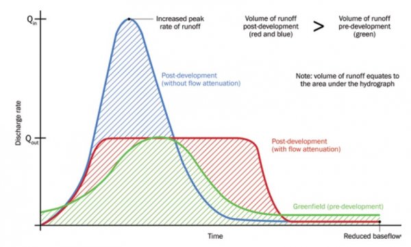
4.5. Volume control
The runoff volume from the developed site for the one in 100 year six hour rainfall event must not exceed the greenfield runoff volume for the same event.
This is an additional measure to the peak flow control, as the additional volume of surface water generated by the development needs to be controlled so that the volume of surface water runoff post development does not adversely affect the receiving system.
As can be seen by the Figure 4.5 Volume Control below, by only reducing the peak flow rate, the volume of runoff is extended over a greater length of time, resulting in higher discharges of surface water volume post-development compared to pre-development. Measures should be proposed to reduce or remove the volume from the site via infiltration, long term storage, receiving proposed sustainable drainage systems features or harvested for use within the development site.
Reducing to the pre-development QBAR greenfield runoff peak flow rates is usually sufficient to achieve volume control for the one in 100 year six hour storm event, which is regarded as the design rainfall event for volume control, on sites with the necessary attenuation storage provided.
For brownfield sites it must also be demonstrated that the designed surface water attenuation also controls the volume of runoff from the post-development site to the pre-development QMED/QBAR greenfield runoff volume for a one in 100 year six hour storm event.
4.6. Pollution control
Sustainable drainage systems design must ensure that the quality of any receiving water body is not adversely affected and preferably enhanced before it leaves site.
Drainage from the proposed surface water scheme must undergo some layers of treatment before discharging off site, this can be in the form of roadside gullies, petrol interceptors, reed beds, silt traps, etc.
The use of sustainable drainage systems within development sites is beneficial due to the pollution control that sustainable drainage systems can offer compared to conventional drainage measures.
The use of petrol interceptors will only need to be used for sites that require 30 or more car park spaces or equivalent area of hardstanding, otherwise, road side gullies are a sufficient measure for smaller sites for pollution control from highways.
4.7. Designing for exceedance
Site design must be such that when sustainable drainage systems features are exceeded due to failure caused by blockages or collapsed pipes or when the system is overwhelmed by excessive flood flows, the exceedance flows do not cause flooding of properties on or off site. This is achieved by designing suitable ground exceedance or flood pathways.
Runoff must be completely contained within the drainage system (including areas designed to hold or convey water) for all events up to a one in 30 year event, with no flooding anywhere on site.
Rainfall in excess of a one in 100 year rainfall that exceeds the designed sustainable drainage systems scheme must not flood any properties or essential infrastructure (pumping station, junction boxes, etcetera) and any exceedance flows are managed within the site that avoid risk to people and property both on and off site, with the design of the site mindful of the topographic levels and highway requirements (cross fall, dropped kerbs) as to not cause flooding to properties from exceedance flood flows.
4.8. Highway drainage
Sustainable drainage systems features within highways and that schemes that wholly manage the drainage from the proposed highways can be adopted by our highway authority and maintained as part of the wider highways maintenance subject to agreement of the highway authority. The incorporation of sustainable drainage systems that involves highway drainage requires the developer either to enter into an agreement under Section 38 of the Highways Act, if involving new development, or an agreement under Section 278 of the Act, if existing highway arrangements are to be modified. It is recommended that discussions are undertaken with the highway authority as early as possible.
4.9. Climate change
Due to changing climate, winters are likely to get wetter and we are likely to experience more extreme weather conditions such as intense rainfall events. As such, an allowance must be made in the sustainable drainage systems design for increased intensity of rainfall.
In its strategic overview role for all sources of flooding (Flood and Water Management Act 2010) the Environment Agency publishes the set climate change allowances to be used in in flood risk assessments and drainage design. Latest guidance sets climate change allowances based on river basin management catchments. You must check that you are working with correct catchments allowances through the catchment map tool on the GOV.UK website.
Use the development lifetime guidance to work out the lifetime of your development. You should consider residential development to have a minimum lifetime of 100 years.
4.9.1 Development with a lifetime beyond 2100
For flood risk assessments and strategic flood risk assessments assess the upper end allowances. You must do this for both the 3.3% and the 1% annual exceedance probability events for the 2070s epoch (2061 to 2125).
Design your development so that for the upper end allowance in the 1% annual exceedance probability event:
- there is no increase in flood risk elsewhere
- your development will be safe from surface water flooding
4.9.2 Development with a lifetime of between 2061 and 2100
For development with a lifetime between 2061 and 2100 take the same approach but use the central allowance for the 2070s epoch (2061 to 2125).
4.9.3 Development with a lifetime up to 2060
For development with a lifetime up to 2060, take the same approach but use the central allowance for the 2050s epoch (2022 to 2060).
Contact us if you are unsure which allowance to use.
4.10. Urban creep
Urban creep describes future expansion within a development and activities such as building extensions and paving gardens. These activities increase the impermeable area of a site and often sit outside of the development control process.
As such all proposed residential developments must have an allowance for this increase in impermeable area of 10% on top of the proposed impermeable area of the development site. The 10% increase should be included as part of the design development area of the submitted calculations.
Alternatively, the urban creep allowance can be added to the percentage increase applied to the site design rainfall can be used to account for both the climate change and urban creep allowances.
5. Construction
Damage caused during the construction phase has the potential to prevent sustainable drainage systems functioning as required, for example contamination by sediments generated during construction. As such appropriate planning must be applied to surface water management during the construction phase.
Temporary mitigation measures should be proposed to control surface water flows from the development during the construction phase. A construction phase management plan should be provided.
6. Maintenance requirements
All drainage systems, including sustainable drainage systems components require regular inspection and maintenance to reduce the risk of failure and ensure effective operation over the lifetime of the development.
Legislation requires that planning authorities ensure, through the use of planning conditions or planning obligations, that there are clear arrangements in place for ongoing maintenance of sustainable drainage systems over the lifetime of the development. Maintenance requirements for proposed sustainable drainage systems are to be agreed with the local planning authority.
There are a range of sustainable drainage systems maintenance schemes available, which must be evaluated on a case by case basis, to ensure that it is applicable, proportionate and practicable for users to operate and maintain for the lifetime of the development. The list below is not exclusive and developers should discuss maintenance proposals as soon as possible with the local planning authority, lead local flood authority and water and sewerage company.
6.1. Adoption and maintenance of sustainable drainage systems by the local water and sewerage company via a section 104 Water Industry Act agreement with that company. The developer should discuss the proposals as early as possible with the local water and sewerage company. Confirmation from the water and sewerage company should be submitted to the local planning authority as part of any planning application.
6.2. Adoption and maintenance of sustainable drainage systems by a local authority. With the exception of the highway authority that can adopt sustainable drainage systems serving highway drainage, we do not adopt sustainable drainage systems. Adoption of highway sustainable drainage systems must be agreed with the highway authority and confirmation provided to the local planning authority as part of any planning application.
6.3. Adoption and maintenance of sustainable drainage systems by the Internal Drainage Board. Five internal drainage boards operate within North Yorkshire, these are;
- Vale of Pickering internal drainage board
- Kyle and Upper Ouse internal drainage board
- Swale and Ure drainage board
- York consortium of drainage boards
- Shire group of internal drainage boards
In local drainage board areas, subject to internal drainage board consent, a maintenance agreement can be entered into, following either payment of a commuted sum or ongoing infrastructure charge. A developer may build (or contribute to) sustainable drainage systems that the internal drainage board subsequently maintain. Often internal drainage boards will only approve a limited number of sustainable drainage systems types and each internal drainage board operates independently, so early conversations with the relevant internal drainage board are essential.
6.4. Maintenance of drainage systems within property curtilages by the homeowner. It must be demonstrated to the satisfaction of the local planning authority that maintenance will be assured for the lifetime of the development. It is not satisfactory to assume that homeowners and subsequent homeowners will be aware of the maintenance requirement and their responsibilities; Those measures must be proposed by the applicant and may include, for example, information provided to the first purchaser of the property and also designation/registration of the sustainable drainage systems so that it appears as a land charge for the property and as such is identified to subsequent purchasers of the property. Any methods involving designation or registering a land charge are to be agreed with the local planning authority.
Sustainable drainage system schemes for individual properties should be wholly located within the boundaries of the receiving property so that maintenance and ownership is understood to be with the receiving property; shared sustainable drainage system schemes should be located in POS / shared spaces under the management of a designated management company.
6.5. Maintenance of sustainable drainage systems within the curtilages of land by the commercial body or organisation that owns or occupies that land. It must be demonstrated to the satisfaction of the local planning authority that the maintenance arrangements and their funding will be in place for the lifetime of the development.
6.6. Inspection and maintenance of sustainable drainage systems via a private maintenance agreement (for instance, private management company). It must be demonstrated to the satisfaction of the local planning authority that the maintenance arrangements and their funding will be in place for the lifetime of the development.
Maintenance under a private arrangement may be subject to a higher degree of scrutiny by the local lead flood authority due to the number of risks involved. The developer should explore the potential risks and costs associated with private management arrangements and should submit the following to the local planning authority:
6.6.1. Details of the organisation responsible for the ongoing maintenance of the sustainable drainage systems for the lifetime of the development
6.6.2. Details of the funding arrangements in place for the inspection and maintenance of sustainable drainage systems. It must be demonstrated how the ongoing maintenance of the sustainable drainage systems for the lifetime of the development will be funded. Information should be submitted which demonstrates where the responsibility will fall should the management company arrangement fails and/or the company ceases to exist.
6.6.3. As built drawings and a maintenance and operation manual for all sustainable drainage systems, including for single property sustainable drainage systems. This must include physical access arrangements for maintenance (ensure an easement of min. 3m to both sides) and establishment of legal rights of access in perpetuity prior to the commencement of any phase of the development. A copy of a maintenance and operation manual for single property sustainable drainage systems must be supplied to the relevant residents.
6.6.4. A plan clearly showing the extent of the adopted area along with easements and rights of way for access to carry out maintenance. If other parties are responsible for different parts of a scheme, this should be clearly shown on the plan.
6.6.5. The maintenance schedule of work - itemizing the tasks to be undertaken and the frequency at which they should be performed so that an acceptable long term performance standard is secured. The schedule should be a living document as it may change, where inspections advise changes to the scheme maintenance requirements
6.6.6. A whole life cost analysis for maintenance over the lifetime of the development and details of financial security to ensure long term maintenance.
6.6.7. Details that ensure soakaways incorporate a no development easement of 5m to all sides of the soakaway to reduce the risk to properties and buildings from seepage and instability.
6.6.8. Details that ensure all attenuation features have a 2m easement to all sides of the asset for access.
Reasons for the required information:
- to confirm that appropriate routine maintenance of the system is being undertaken
- to confirm that the system is continuing to operate effectively
- to identify any remedial works required
- to provide a consistent record of the condition and performance of the system.
- to prevent the increased risk of flooding and to ensure the future maintenance of the sustainable drainage system
See Susdrain – sustainable drainage systems maintenance and adoption options (England).
7. Sustainable drainage systems components
There are several options for the use of sustainable drainage systems within development sites including rainwater harvesting, water butts, green roofs, permeable surfacing, infiltration, filter drain, filter strips, swales, controlled inlets and outlets, detention basins, infiltration basins, ponds, wetlands, geocellular / modular systems, pipes / subsurface drainage and storage, bioretention systems, silt traps and interceptors.
Guidance for the construction of these sustainable drainage systems can be found in the Ciria SuDS Manual C753, additional information for development proposals is highlighted below.
7.1. Permeable surfacing
Permeable surfacing can provide a suitable pavement for pedestrians and vehicular traffic while allowing surface water storage, conveyance and infiltration. There are three main types of permeable paving design used for varying infiltration rates for the site. Easements are not required for permeable paving.
- Type A - Full infiltration – Development sites that have shown good viable infiltration rates for the soils can be built with no formal outlet of drainage, allowing surface water runoff from the incoming property down pipe or directly throw the paving to infiltrate to the soil via the sub base of the permeable paving, thereby acting as a large soakaway. The sub-base should be designed to contain the 1 in 100 year rainfall event plus climate change without flooding.
- Type B - Partial infiltration – for sites with a poor yet viable infiltration rate, it may be necessary to add an additional piped outfall to aid drainage whilst still allowing for infiltration through the sub-base. This method should be utilised when the sub-base of the permeable paving would become too large to contain the one in 100 year plus climate change rainfall event.
- Type C - No infiltration – Permeable paving can still be used for sites with very poor, unviable infiltration rates below the threshold, provided that the sub-base material of the permeable paving is lined with an impermeable geo-textile layer and a formal outlet pipe is provided in the design. As the permeable paving sub base has a formal drainage connection, the sub base will not provide adequate storage and should not be included in the attenuation calculations unless the outlet flow is controlled and designed to attenuate flows. As the surface water is filtered through the permeable paving sub base, the proposed outlet flow control can be smaller than the minimum adoptable flow control size.
7.2. Infiltration
Soakaways can store surface water run-off and allow for its efficient infiltration into the adjacent soil. It must be demonstrated that the groundwater level at the site always remains a minimum of 1m below the base of any soakaway. Sustainable drainage systems features that utilise infiltration should only be used where infiltration is a viable method for disposal of surface water as per the guidance in section 4.1.1.
Soakaways in private garden spaces should not cross land boundaries and ownership and maintenance of the soakaway / infiltration feature should be made known to the future/existing landowner.
Soakaways will require a 5m easement to all sides of the soakaway from all buildings and highways (BRE 365 Digest). Attenuation features will require a 2m easement for access to all sides of the sustainable drainage systems feature.
7.3. Pumping stations
Surface water pumping stations should only be used by exception. It is recommended to discuss the proposals as early as possible with the local lead flood authority and waste and sewerage company. A suitable exceedance flow path must be demonstrated in the event of failure or exceedance of the pumping system.
8. Planning application requirements
8.1. Outline planning applications
Flood risk and drainage are not a reserved matter and sufficient detail should be submitted with an outline or full application to determine if the development is suitable in terms of the level of flood risk present and which drainage options and outfalls are available.
It must not be assumed that sustainable drainage systems can be dealt with as a reserved matter and at outline application stage it must be demonstrated that surface water can be successfully managed for the proposed development and not cause or increase flood risk both on and off site.
The following requirements are advised by ourselves and should be met as a minimum for all development sites, not just for outline applications:
Runoff destinations:
- All development sites must apply the drainage hierarchy as set by Building Regulations Part H and adequate percolation tests to BRE 365 Digest must be submitted to determine the viability of infiltration for the development site.
- Provide a Site Location / Indicative Drainage Layout drawing with the outfall identified, including any existing sewers and watercourses on site. Topographical survey of the existing site’s catchment to include contours at 1m interval and existing surface water flow routes, drains, sewers and watercourses.
- Determination of the greenfield or brownfield status (with adequate evidence to prove the site has existing, positively drained sewer systems for brownfield sites).
- For brownfield sites, a pre-existing drainage survey must be submitted and connection of the new development drainage highlighted.
Flood risk:
- A National Planning Policy Framework compliant flood risk assessment for all developments should be submitted to the local planning authority. Only sites within flood zone one and are less than one hectare in size do not require an flood risk assessment. Mitigation measures should be proposed for sites within flood risk zones two and three or at risk from surface water flood risk.
Peak flow control:
- Indicative greenfield runoff rate calculations using IH124, interim code of practice for sustainable drainage systems or flood estimation handbook techniques of estimation. Quick storage estimates of the necessary attenuation are required as a minimum using greenfield runoff rates.
- For brownfield sites, the resultant peak flows rates should be reduced to greenfield runoff rates or as near as possible, if this cannot be achieved then indicative calculations of the existing pre-development flow rates are required via a hydraulic model of the existing drainage system or the rational method of calculation. This should limit the post development flow rate to the QBAR pre development flow rate with a 30% reduction in flow. The post development flow rate should be restricted to all flood events up to the one in 100 year flow rate with a climate change allowance applied to the design rainfall event.
- Hydraulic calculations of the finalised design can be dealt with by a planning condition.
Highway drainage:
- To be agreed with our highways, drainage from the proposed highways should be identified within the drainage layout for the development site.
Climate Change:
- Climate change allowance to be applied as per Section 4.9 of the design document.
Urban Creep:
- A 10% increase in impermeable area should be applied to the design area within the submitted finalised calculations (by planning condition).
8.2. Full planning applications, reserved matters, discharge of conditions
In addition to all of the information required for outline approval, it is required for full, reserved and discharge of conditions applications that the following additional information will be submitted:
Drainage layout:
- Finalised drainage layout drawings with agreed drainage outfalls, peak flow rates, required attenuation storage and finished floor levels. Any updated/finalised calculations must be submitted for approval. Hydraulic calculations of the designed drainage system using the calculated peak flow rate and necessary attenuation.
Volume control:
- Calculations are required to prove that the site does not increase the amount of runoff volume from the development in a one in 100 year six hour design event.
Pollution control:
- A site drainage layout should be submitted that highlights any sustainable drainage system features or pollution control measures that will manage the risk of pollution originating from the development site.
Designing for exceedance:
- An exceedance flowing routing map of the site which shows where flooding is likely to occur in the event that the designed drainage system is exceeded or fails. The routing map should indicate direction of flood flows, highlighting areas that will flood and to what depth.
Construction:
- Finalised drainage details of the construction of the drainage layout, cross sections of the proposed sustainable drainage schemes, location of the proposed flow control and appropriate measures for access and easements applied to the drainage layout.
Maintenance:
- Information that supports the long term maintenance for the lifetime of the development, confirming which authority, management company or private owners will be responsible for the proposed drainage scheme.
Note that, dependent upon the complexity of the site and development proposals, additional information may be requested for full and reserved matters applications as part of a planning condition and are required for later discharge of conditions. However, it is preferable that all information is submitted as early as possible for consideration as to reduce the risk of being unable to discharge the relevant planning conditions.
8.3. Planning applications checklist
Below is a typical list of required documents to aid the lead local flood authority’s consultation for each stage of the planning process. The list of documents is not exhaustive and further documents / submissions may be required by the lead local flood authority.
| Pre-application | Outline | Full | Reserved matters | Discharge of conditions | Minimum documents submitted |
|---|---|---|---|---|---|
| Yes | Yes | Yes | Flood risk assessment or statement, appropriate to site and associated risk | ||
| Yes | Yes | Yes | Drainage strategy or statement and sketch layout plan (with discharge point) | ||
| Yes | Preliminary layout drawings (existing drainage for brownfield sites) | ||||
| Yes | Preliminary hydraulic calculations (quick estimates of green/brownfield runoff rates and attenuation) | ||||
| Yes | Preliminary landscape proposals (for exceedance routes) | ||||
| Yes | Yes | Ground investigation report (of sufficient detail to determine if infiltration is viable at the site) | |||
| Yes | Yes | Condition and capacity survey of receiving watercourse to confirm suitability for surface water disposal | |||
| Yes | Yes | Yes | Evidence of third party agreement to access a third party system (in principle) | ||
| Yes | Yes | Maintenance program and ongoing maintenance responsibilities | |||
| Yes | Yes | Detailed development layout | |||
| Yes | Yes | Yes | Detailed flood and drainage design drawings, including discharge point, flow restriction and attenuation size | ||
| Yes | Yes | Yes | Full hydraulic model of proposed drainage | ||
| Yes | Yes | Yes | Full ground investigation reports, including infiltration results | ||
| Yes | Yes | Yes | Detailed exceedance flow routes map, with necessary mitigation measures and landscaping details | ||
| Yes | Yes | Yes | Development management and construction phasing plan |
9. Example drainage calculation scenarios
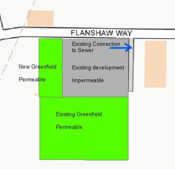
9.1. New greenfield site
- As a new development site, peak flow rates will be restricted to the greenfield QBAR rate for all flood events up to the one in 100 year plus climate change plus urban creep event,
- Calculate the greenfield runoff rate using IH124 or FEH methods,
- Restrict the proposed drainage peak flow rate to the calculated greenfield runoff rate and calculate required attenuation.
9.2 Brownfield site (no increase in impermeable area)
The proposal is for a redevelopment of an existing site, with an active, positively connected drainage system. The proposal will not change the impermeable area of the site. The greenfield area can be discounted as naturally draining into the ground as per pre-development.
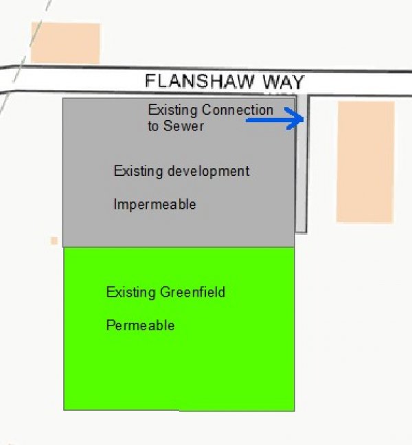
- Calculate the existing brownfield runoff rate using a hydraulic model of the existing drainage system, determine the QBAR brownfield rate of the existing site
- Utilise existing connection to sewer
- Restrict the proposed drainage peak flow rate to the calculated existing brownfield QBAR runoff rate for all flood events up to the one in 100 year plus climate change plus urban creep (if appropriate) event
- The proposed peak flow rate must also be reduced by a minimum of 30% from the existing flow rate
- Calculate required attenuation
9.3. Brownfield site (decrease in impermeable area)
The proposals are for a redevelopment of an existing brownfield site, which will reduce the overall impermeable area of the development site. The same drainage principles apply as in Section 9.2, which should be easier for developers to provide the necessary attenuation.
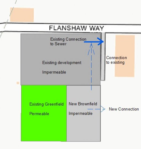
9.4. Brownfield site (increase in impermeable area / mixed previous land use)
The proposals are for a redevelopment of an existing brownfield site, which will increase the overall impermeable area of the development site by incorporating an existing greenfield area.
Restrict the existing impermeable area to the calculated brownfield QBAR runoff rate and the new area of development to greenfield runoff rates
The existing area would be regarded as brownfield, as per section 9.2, the new additional impermeable area should be treated as a new development and restricted to a calculated QBAR greenfield runoff rates, as per section 9.1. The developer may seek to connect the new impermeable area to the existing sewer connection at the greenfield QBAR peak flow rate (as an addition to the existing peak flow rate minus 30% from the existing brownfield part of the site) or to a new connection at the greenfield QBAR peak flow rate.
9.5. Brownfield site with a new connection
Some brownfield sites may require a new connection to a different receiving water system than the connection that the site currently utilises; these sites are to be considered as a new impact on the receiving drainage system / watercourse and should be considered as a greenfield development.
10. Contact details
For all enquiries please contact us.